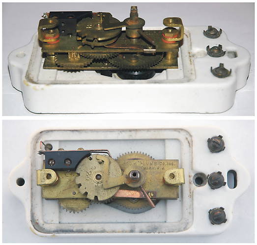
There are two code wheels and two contact arms or wipers inside the Postal call box. Each of these forms an electrical circuit. One circuit is normally open, the other normally closed. So this call box can be used either in a series loop (using the normally closed circuit, like a fire alarm circuit) or with a number of call boxes in parallel (using the normally open circuit). The right hand terminal screw (bottom in the picture) goes to the frame of the motor, which is in common with both code wheels. Notice a copper wiper that forms a solid connection between the motor frame and the bottom of the lower code wheel. You can see slots on the upper, normally closed code wheel, and teeth on the normally open code wheel beneath it. The upper code wheel is stamped "24". Sure enough, there are two then four slots on the upper wheel, and two then four teeth on the lower one. The middle terminal goes to the normally closed wiper, which rides on the upper code wheel. As the code wheel turns, its wiper drops into the slot, breaking the circuit. The left hand (top) terminal goes to the normally open wiper, which rides on the lower code wheel. As this code wheel turns, its wiper touches the teeth, completing the circuit. In either case, turning the handle and releasing it winds up a spring in the motor. This turns the code wheels, generating the series of 2 then 4 electrical pulses. When received at the Postal Telegraph office, this 2-4 code identifies which customer has a telegram ready for pickup. A messenger is then sent to get it. I replaced the previous picture with this one. I think this is clearer, as it shows two views of the code wheels. |